|
The Install
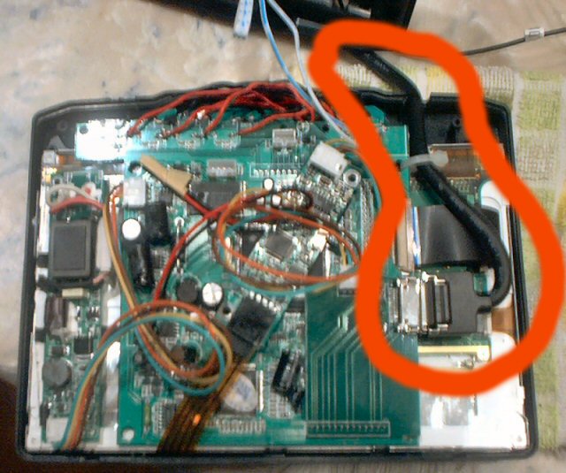
In this section I am going to outline the install process of putting the Xenarc 700TSV into the in-dash kit provided by Digital Worldwide. Some of the images are taken from the Digital Worldwide website since my camera decided to quit on me.
DISCLAIMER: If you decide to attempt this modification it is at your own risk. I am not responsible for any typos or errors in this document which may cause your LCD screen to malfunction in anyway. Also, realize that in doing this modification you will be voiding any type of warranty that you have on the product.
With that all out of the way let's start. The first step is to remove the housing on the Xenarc 700TSV. Be very careful not to scratch the LCD screen or you will have one big mess. I would recommend placing the unit face-down on some type of sponge or soft pad. The screws holding the housing on were located on the back. Simply unscrew them and the back housing should separate from the LCD. Once you remove the rear housing there will be clips holding the LCD onto the front cover, these will need to be removed as well.

Once this is all completed you should be able to remove the LCD, touchscreen, and controller card from the housing.

For the next step we will be working with the In-Dash kit. We will be utilizing the existing LCD controls on the kit (power, AV selection, volume, etc) to control the Xenarc 700TSV. To do this the housing will need to be separated by unscrewing the screws located in the rear of the housing, the same location as on the Xenarc 700TSV. After you separate the two pieces of the housing, you will need to locate the two screws that are holding the controller board for the buttons (power, volume, etc). This can easily be located, because it is exactly behind the actual buttons on the LCD housing of the kit. Once you remove the controller board, the actual buttons will become visible. Be careful not to lose any of them.

Now, take the button controller board that you just removed and set it aside to work on. You will want the side that was facing the buttons, or front of the housing, to face you. The next thing we will be doing is soldering 10 wires, one on each side of the buttons. Be sure to solder them to the metal connector coming out of each button. When completed it should look like the following.

When completed soldering the wires, you can install the board back onto the front of the housing. You can also at this point install the touchscreen and LCD into the housing. In order to properly fit both, you will probably need to cut away some of the plastic clips at the top of the housing, once properly fitted, install some double-sided tape to keep the unit intact.

Now we need to remove the existing buttons on the 700TSV controller board and attach the new wires we just soldered onto the controller board included with the kit. To remove the existing buttons on the 700TSV, simply heat each corner of the button, where the metal connector comes out; slightly pull on the corner you are heating until the metal connector pulls out. Repeat these steps for each corner of every button. Once you have completed the removal of the buttons, it should look similar to this.

(Picture taken from the Digital Worldwide website)
Once you have removed the buttons off the 700TSV controller board, you will need to solder the wires to connect the new buttons included with the housing to the existing 700TSV button locations.

(Picture taken from the Digital Worldwide website)
Now to connect the power you will need to remove the existing power connector on the 700TSV the same way you did the buttons and solder the first two wires of the 4 wires coming out of the rear of the housing kit as shown below.


(Picture taken from the Digital Worldwide website)
Once you have done this, you will need to cut a notch into the rear plastic housing to allow the video cable to connect to the board. Note: The picture below shows the notch in the front housing, but be sure to cut it in the rear housing as it will fit better when slid into the unit.
(Picture taken from the Digital Worldwide website)
Once all of this is completed make sure all the wires are nicely tucked into the housing and put the unit together with the screws.

(Picture taken from the Digital Worldwide website)
Now comes the fun part of routing the black video cable through the unit. The first step you will need to do is cut a hole in the right hand side of the plastic frame inside the unit to attach a wire tie to hold the cable, the easiest way of doing this I found was to use a soldering gun to melt right through the plastic.

(Picture taken from the Digital Worldwide website)
After doing this you will need to drill two holes into the bottom of the unit. These holes will act as holders for the cable. Be sure to drill the holes small enough so that the head of a wire tie will not go through them.

(Picture taken from the Digital Worldwide website)
After drilling the holes, take two wire ties and install them as shown below. To do this you will need to remove the back cover of the unit.
 
(Pictures taken from the Digital Worldwide website)
Once installed slide the LCD into the unit until you get a bunch in the cable, when this occurs, you will need to take the cable and pinch it with some pliers to allow it to properly fold back when pushed into the unit.
 
(Pictures taken from the Digital Worldwide website)
After completing this you should be able to push and pull the LCD in and out of the unit without much problem. After having completed this you can now route the two cables (the video which attaches to the LCD, and the power cable which comes with the kit) through the existing hole in the rear of the unit.

(Picture taken from the Digital Worldwide website)
At this point you should be completed. |